

Ask a Question
Broadband RF Amplifiers in EMC Immunity Testing

Michael Hempel - Rohde & Schwarz

An electrified society
Electronic devices are playing an increasingly important role in almost every area of daily life. In 2018, there were around 10 devices in a typical household in the USA; 5 years later, this figure had risen to 17 (source: Consumer Electronics Dashboard, Parks Associates, 2024). And because these figures only take into account wireless electronics (mobile communications, Wi-Fi, Bluetooth), the number of electronic devices per household is actually even higher. This electrifying trend isn’t just limited to our private lives; the same is happening in industry, aviation, medicine and the education system.
EMC testing is important for industry and society
All electronic devices have the potential to interfere with or be interfered with by other electronic devices. There is a difference, however, between radiated emissions (which travel through the air) and conducted emissions (in wires). The effects of electromagnetic disturbance range from barely audible buzzing or visible flickering to device failure and even permanent damage.
More electronic devices, often in close proximity to each other, mean a need for more measures to detect and measure disturbance between devices. The objective is either to completely eliminate electromagnetic disturbance or at least limit it.
Electromagnetic compatibility (EMC) is the ability of electronic devices to function properly in a specific electromagnetic environment without interfering with it or being interfered with themselves. Especially in today’s world, with its numerous complex and connected electronic products, disturbance-free coexistence is a must.
Regulatory obligations and standards
The growing importance of electromagnetic compatibility has led to numerous EMC standards and regulations. They can be broken down into government, military and industrial EMC standards. They are defined by the committees of the relevant standards organizations such as CISPR, IEEE, ISO and MIL. In many parts of the world, electronic products have to demonstrate compliance with the relevant EMC standards before they can be marketed or sold. As a result, many companies have integrated EMC testing into their product development cycle.
Emission testing and immunity testing
EMC testing can be divided into two general categories: emission testing and immunity testing (see Fig. 1).
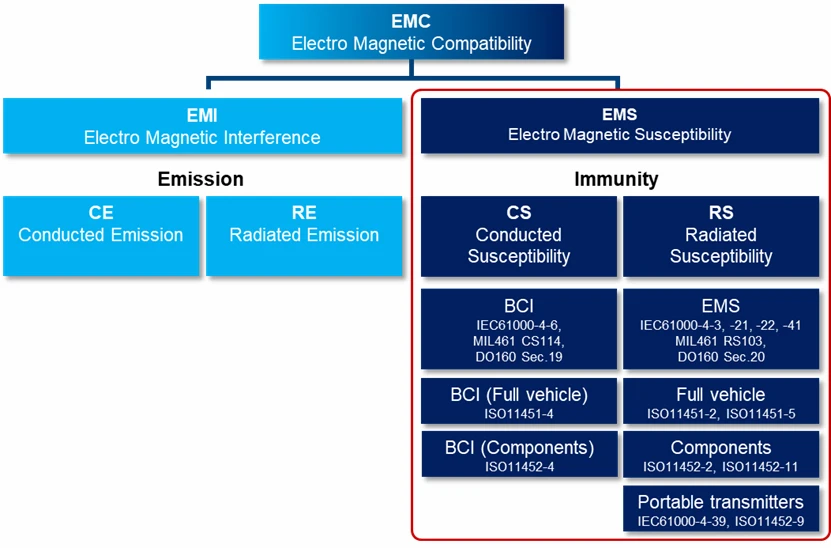
Fig. 1: Classification of EMC tests and standards. Broadband amplifier systems are mainly used in electromagnetic susceptibility (EMS) tests.
Emission testing (disturbance) measures the electromagnetic signals emitted by the equipment under test (EUT). It can thereby be determined whether these emissions exceed the permissible limits, which could cause problems for other devices in their vicinity. The purpose of immunity testing, on the other hand, is to verify that a device continues to function properly when exposed to (often significant) amounts of radio frequency energy.
There are numerous examples known of electronic devices malfunctioning or failing at high RF energy levels – in some cases, malfunctions have even led to injury and death.
Broadband amplifiers are essentially used to generate the high-energy disturbance field. Fig. 2 shows an immunity testing system: The contents of this 19-inch rack include broadband RF amplifiers for four frequency ranges from 9 kHz to 18 GHz (two R&S BBA300 units and two R&S BBA150 units).

Fig. 2: Example of an immunity testing system employing R&S BBA broadband RF amplifiers.
Immunity testing overview
In immunity testing, an electronic product, such as a device or a vehicle, is exposed to defined levels of radio frequency energy over a wide frequency range in order to determine whether the product still functions properly.
This radio frequency energy can be conducted directly into the EUT as a disturbance signal via the connected cables (conducted immunity test) or radiated as an electromagnetic field through the air onto the EUT (radiated immunity test).
In the conducted immunity test, a disturbance current is injected using a current probe surrounding the cable in order to test the robustness of the electronic input and output circuits of the EUT.
In the radiated immunity test, a defined electromagnetic field – which covers a homogenous field area of 1.5 m x 1.5 m – for the test frequency in question is generated by the antenna at a fixed distance of, e.g., 3 m from the tip of the antenna. The EUT is located in this field area. By gradually increasing the test frequency (sweeping) within the frequency ranges specified by the standards, the immunity of the EUT to the disturbance frequency can be tested.
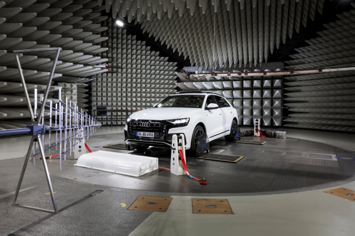
Fig. 3: EMC chamber for radiated immunity tests on entire vehicles.
Depending on the product and standard, electric field strengths of 3 V/m to 200 V/m may be required for certain frequency ranges between 9 kHz and 18 GHz. In the automotive sector, this can even extend up to 600 V/m (see Fig 3).
Test setup for immunity testing
Fig. 4 shows a typical system setup for immunity tests. These are usually carried out in a screened EMC test chamber. A signal generator acts as the signal source. A broadband RF amplifier system amplifies the signal that is transmitted to the EUT by a broadband RF antenna. For conducted tests, a current probe does the job of the antenna. A directional coupler and a power meter ensure that a defined RF power is generated. A measuring probe and a measuring receiver validate that the field strength required by the EMC standard is actually present at the EUT. Control software manages all the equipment involved and carries out the test procedures required.

Fig. 4: Typical system setup for an immunity test. Most of the test and measurement equipment is located in a control room. The measurement itself takes place in a screened EMC chamber.
The RF power required depends on the EUT and numerous other factors, and is often in the hundreds or even thousands of watts. Since signal generators cannot produce such high power, broadband RF amplifier systems are connected downstream.
Requirements for broadband RF amplifiers
EMC test labs often cover many EMC standards and perform tests in very different frequency and power ranges. The alternative to a complex RF amplifier system consisting of countless narrowband RF amplifiers is an ultrabroadband RF amplifier with scalable output power. Ideally, it should have a modular structure to implement customer-specific systems flexibly.
One of the many other requirements for broadband amplifiers is robustness against mismatch at the RF output.
Mismatch and VSWR
The components on the path to the EUT (plug, cable and antenna) do not have a 50-ohm impedance at their interfaces and are therefore not optimally matched. This results in reflections of the generated RF power that return to the amplifier. Additionally, the EUT reflects. This causes the system to lose energy, which the RF amplifier must compensate for with higher RF power in order to achieve the required nominal power. At the same time, it must be robust enough to withstand the reflected energy.
The metric for this in RF engineering is the voltage standing wave ratio (VSWR). It defines the standing wave ratio of the forward wave with its nominal power and the reflected wave with the reflected energy. For example, a system with a VSWR of 6:1 reflects half of the energy (poor matching), while a VSWR of 2:1 reflects 11 % of the energy (good matching). If an RF amplifier can deliver its nominal power even in systems with high VSWR values, this is a sign of quality and indicates that sufficient transistor reserve has been installed.
Linearity and compression point
The linearity of the RF amplifier, its output power at the 1 dB compression point and its harmonic performance are three other important performance parameters.
Every RF amplifier has a characteristic curve that corresponds to the amplification factor and is ideally linear. This means that at a certain input level, the amplifier generates a higher output level. Since RF amplifiers cannot generate infinite power, they saturate above a certain input level and the output signal is compressed. The point at which the output signal is compressed by 1 dB compared to the ideal, linear level is called the 1 dB compression point. The output power at the 1 dB compression point is referred to as P1 dB. Up to this point, the amplifier is still approximately linear; above this point, the level of harmonic disturbance increases sharply in relation to the fundamental. The harmonic performance should therefore always be specified at the compression point.
Harmonic performance
In EMC testing, RF amplifiers are expected to distort test signals as little as possible in order to precisely validate the performance parameters of the EUT. One way of measuring this distortion is the harmonic performance. Harmonics are the spectral components of the fundamental. The second and third harmonics in particular, can contribute to disturbance due to their higher levels. The difference between the level of the harmonics and the fundamental is described as a characteristic number. In EMC testing, the standard value of –20 dBc and better at the 1 dB compression point has become established as a requirement for amplifiers in order to ensure a maximum value of –6 dBc at the EUT in accordance with EN 61000-4-3.
Noise
The noise figure is a key parameter for low-noise amplification. In EMC testing, the significance of the amplifier's noise figure depends on the EUT. EUTs with radio interfaces require good noise power from the amplifier, or else the radio link to the EUT may be disturbed or interrupted. The noise performance of the amplifier is usually characterized by the noise figure in decibels [dB]. The equation of the noise figure includes the bandwidth of the amplifier. This is because the noise figure is the difference between the noise output of the actual amplifier and the noise output of an ideal amplifier with the same total gain and bandwidth. It is therefore better to define the noise power with a normalized bandwidth independent of the amplifier bandwidth. The noise power density [dBm/Hz] indicates the power of the noise in a bandwidth of 1 Hz around the carrier frequency.
Constant or variable envelope?
In order to select an RF amplifier with the right output power, further criteria such as the envelope, time response and bandwidth of the test signal must be considered. Test signals are divided into two groups: signals with a constant envelope and signals with a variable envelope. Constant envelopes occur, for example, with CW signals and FM, PM and PSK modulated signals. Signals with a variable envelope are, for example, AM modulated signals, complex multicarrier signals (such as OFDM with higher order phase and amplitude modulation) and band-limited white noise.
The envelope of the test signals determines whether the amplifier requires reserves for signal peaks; this is reflected in the crest factor (ratio of the peak value of a signal to its effective average value). Signals with a constant envelope do not require additional power reserves. Their crest factor is 0 dB.
Crest factor and envelope
Test signals with a variable envelope can result in crest factors of up to 15 dB. For example, an AM signal with 80 % modulation depth has a crest factor of 5.1 dB, one with 3 tones has a crest factor of 14.6 dB and a pulsed CW signal has a crest factor of 3 dB. These crest factors require additional power reserves, which must be taken into account when calculating the required P1 dB power of the amplifier. For distortion-free amplification, the peak power of the signal must not be greater than the P1 dB power of the amplifier.
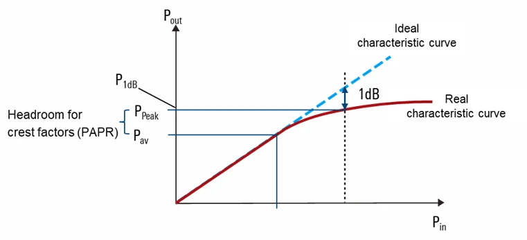
Fig. 5: When dimensioning the required P1 dB power of the amplifier, make sure there are sufficient reserves (headroom). The peak power of the modulated signal should not exceed the P1 dB power.
Taking the test signal bandwidth into consideration
The required bandwidth of the test signal has an impact on the dimensioning of the required P1 dB power. An RF amplifier can only generate a certain amount of energy, and this energy is either concentrated on a single tone or frequency or, in the case of broadband signals, is distributed over a specific bandwidth. The average power output of the amplifier per Hz is therefore ten times the logarithm of the bandwidth of the signal, less than the average power of a single-tone signal. This means, for example, that the average power of a 100 MHz wide noise signal is 80 dB lower than that of a pure sine wave signal with the same aggregated power.
Summary: requirements for RF amplifiers
The following points can be taken from the large number of EMC standards as the most important requirements for RF amplifiers for immunity testing:
- Frequency range and power: Amplifiers should provide sufficient power over a very wide frequency range to generate the required field strengths at each frequency point, which can reach up to 600 V/m depending on the standard and application.
- Linearity and low distortion: Most EMC tests require high linearity over the entire frequency range. This minimizes signal distortion so that the test results are not affected. The typical limit for harmonic distortion is –20 dBc at the 1 dB compression point.
- High mismatch tolerance: Since the load (e.g., a vehicle or EUT) is not always optimally matched, amplifiers must be very robust against reflections and operate stably even in systems with high VSWR values (up to 6:1).
- Modulation types: Amplifiers should be able to amplify different types of modulation, such as CW, AM and PM or complex signals such as OFDM with variable envelopes. Signals with a variable envelope require additional power reserves (headroom) to cover peak power.
Edit an Article
Latest News


Technical Articles
Login to EMC Directory to download datasheets, white papers and more content.

Create an account on EMC Directory to get a range of benefits.
 Please wait...